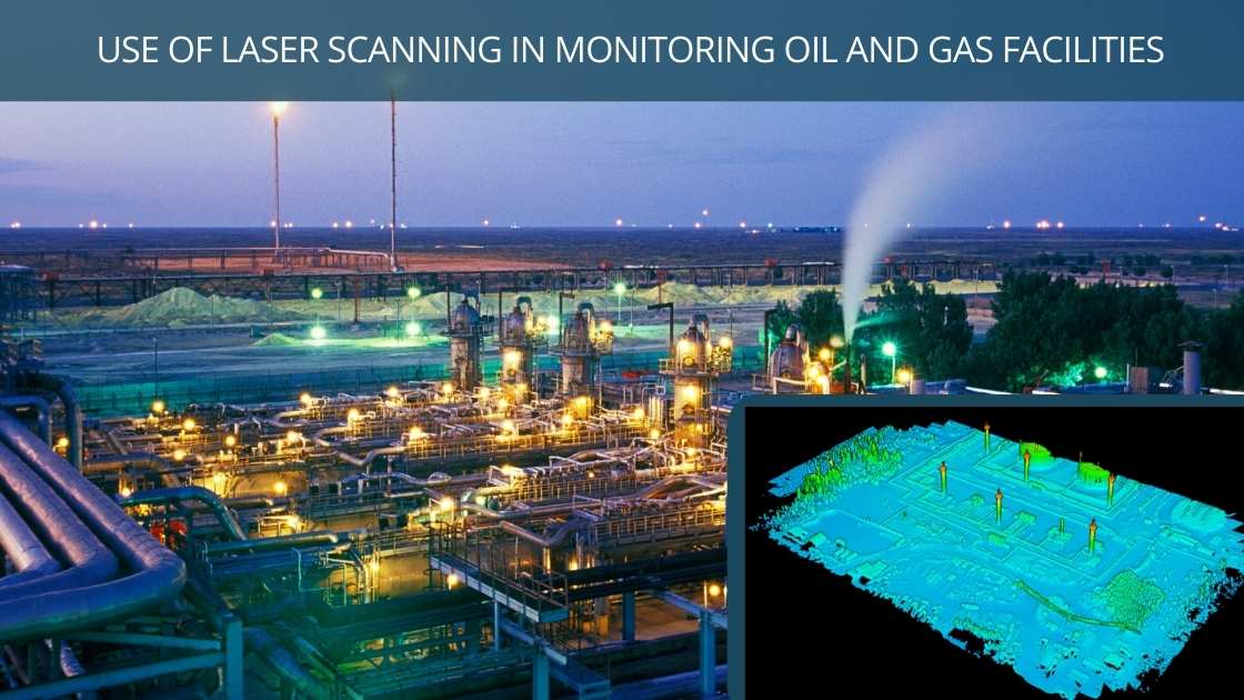
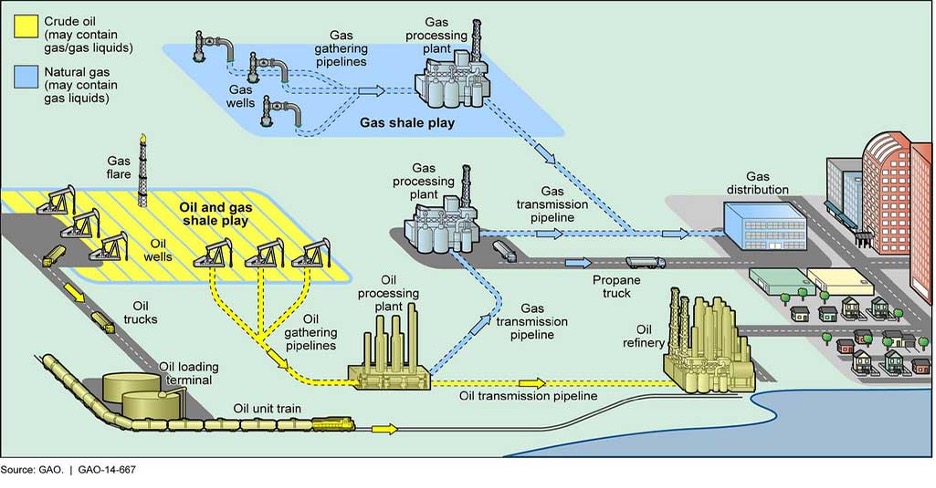
USE OF LASER SCANNING IN MONITORING OIL AND GAS FACILITIES
Oil and gas facility monitoring is essential in optimizing operational and maintenance (O&M) solutions and results in significant cost savings.
There are several types of oil and gas facilities:
- Point or compact
- Average
- Linear
- Large
Accordingly, there are the following types of monitoring:
- Natural site geometry
- Artificial structure geometry
- Dangerous processes
- Environment
These tasks are different both in typology and in accuracy and scope. For instance, 5 to 50-mm precision is required for monitoring the geometry of artificial structures (1 to 30-50 ha.)
Environmental monitoring of a production field can cover up to several tens of thousands of km2 detailed at the one-meter level or less.
In most monitoring tasks, multiple types of monitoring and high-precision remote sensing are required to solve the problem.
Laser Scanning Methods
Modern high-precision methods include airborne laser scanning (ALS), mobile (MLS), and terrestrial laser scanning (TLS).
During airborne laser scanning, pulses of light, usually produced by lasers, are emitted from an instrument on an aircraft and directed to the ground.
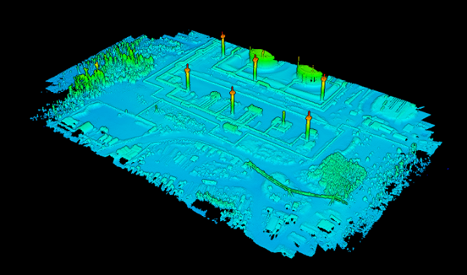
Thus, the object of scanning is covered with numerous laser reflection points with known coordinates. A high-precision digital elevation model (DEM) or terrain model (DTM) is built based on these data.
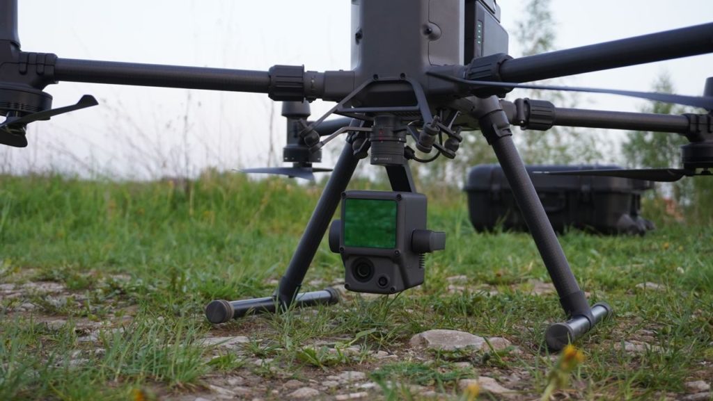
Objects are photographed simultaneously with laser scanning using the DJI Zenmuse L1 laser scanner. The resulting georeferenced photos merge into a seamlessly integrated mosaic, which allows the point cloud to be colored in.
Characteristics of Laser Scan Data
The DJI L1 laser scanner has the following characteristics:
- Detection Range: 450m (80% reflectivity, 0 klx) / 190 m (10% reflectivity, 100 klx)
- Effective Point Rate: 240,000 pts/s
- Supports 3 Returns
- Line Scan Mode and Non-repetitive Petal Scan Mode
Fact #1
Using laser scanning allows us to penetrate the tree crowns with a narrow beam that receives reflections both from the crown and from the underlying surface, which is not possible with passive methods.
Fact #2
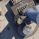
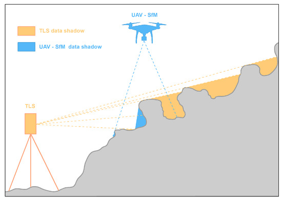
The most convenient method of surveying extensive facilities is airborne laser scanning. Mobile or terrestrial scanning can be used for detailed scans of complex facilities.
Guidelines for collecting data for monitoring various types of facilities
Methods, objects, and tasks

In some cases, there is no alternative to laser scanning
In some cases, laser scanning can be applied to several types of objects and tasks at once. But is it economically feasible?
In some cases, there is no alternative to laser scanning due to its unique combination of precision, completeness, and speed requirements. Furthermore, laser scanning is often more affordable, sometimes several times less expensive, than classical geodesic surveying.
Recommendations by object type
|
Facility type |
Scale |
Acceptable data acquisition methods |
|
Point (individual oil pumping stations (OPS), remote scanning (RS),[Y1] compressor stations (CS), port complexes, etc.) |
1:50 – 1:500 |
TLS, MLS |
|
Average (oil refineries, CS and OPS, sections of passages under large rivers) |
1:50 – 1:500 |
TLS, MLS, ALS |
|
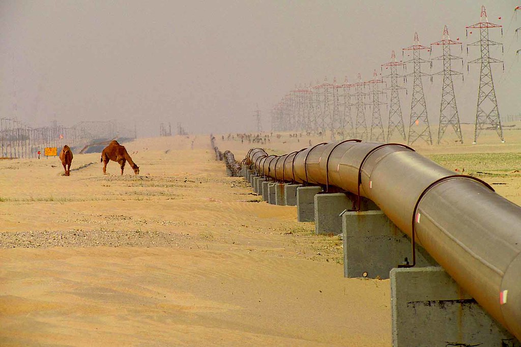
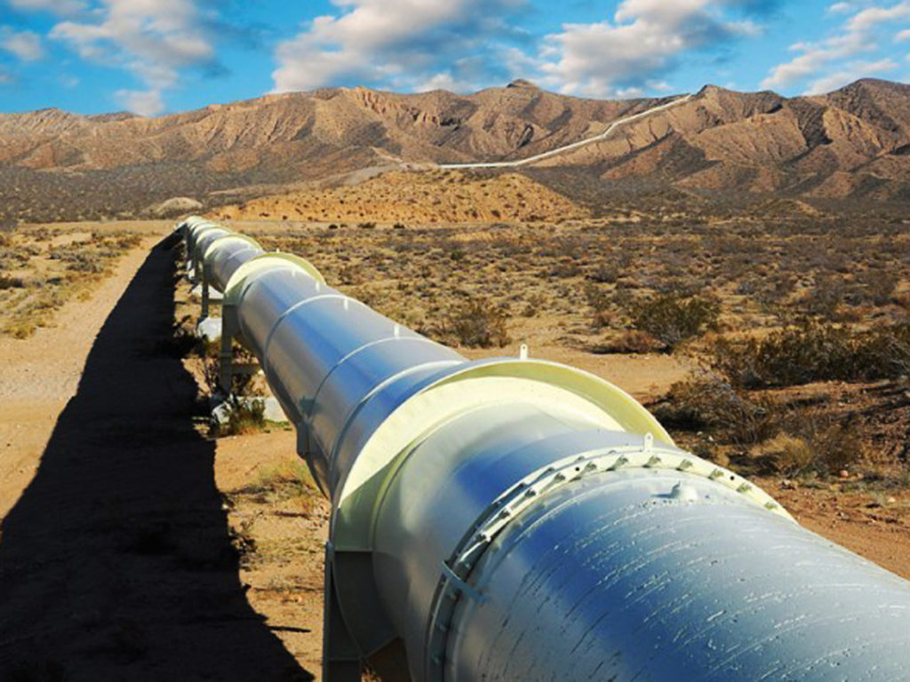
Linear (pipelines, communications – power transmission lines next to auto highways, highways) |
1:500 – 1:5000 |
ALS, radar interferometry, optoelectronic space surveying |
|
Large (licensed sites, deposit fields) |
1:10 000 – 1:25 000 |
ALS, radar interferometry, optoelectronic space surveying |
Recommendations by task type
|
Type of monitoring |
Scale |
Acceptable data acquisition methods |
|
Natural site geometry (relief, vegetation, hydrography) |
1:500 – 1:5000 |
TLS, MLS |
|
Artificial object geometry (facilities, structures, excavations) |
1:50 – 1:2000 |
TLS, MLS, ALS |
|
Dangerous processes |
1:1000 – 1:10000 |
ALS, radar interferometry, optoelectronic space surveying |
|
Environment |
1:10000 – 1:25000 |
ALS, radar interferometry, optoelectronic space surveying |
As a result of these advantages, airborne laser scanning (ALS) is often preferred over conventional visible-range satellite surveying for monitoring purposes.
Integrated (combined) methods of laser scanning and satellite surveying
The application of various remote sensing techniques for monitoring information support purposes can be conceptualized in several ways.
The most straightforward method for monitoring compact objects is to track their geometry using TLS or, less commonly, mobile laser scanning (MLS).
A standard or previous state of the object is compared automatically or manually with the materials of these surveys. Using classic geodetic methods, these zones can be tracked more frequently once potential zones of change have been identified.
For more extensive facilities, ALS is one of the most recommended scanning methods.
ALS may be repeated once every 2-3 years for pipelines in sparsely populated areas, but in hazardous geo-engineering areas, it may be repeated as frequently as 2-3 times a year.
This operational scheme allows taking advantage of the best features of all methods. Thus, by using ALS at the initial stage, one can create a high-precision DEM at absolute altitudes (above sea level).
After each survey, relief altitude displacements are added to the high-precision DEM created from ALS data using radar interferometry, measuring vertical displacements of several millimeters. This allows the DEM to be updated every few weeks. Meanwhile, the DEM accuracy remains between 1:1000 and 1:2000, and the radar survey cost remains the same. This also applies to ultra-detailed space photography.
Furthermore, the above-described survey can monitor hazardous processes such as slope gravity, erosion caused by water, karst, subsidence, sea abrasion, and cryogenic processes.
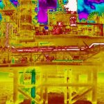
The first step is to conduct an ALS with simultaneous photography of the entire surveyed area in both the visible and thermal range (linear or area objects).
The recommended parameters for topographic mapping with the L1 are:
- Mission Planning Methods: Aerial mapping (Terrain Follow if needed. See Terrain Follow section, below, for more details). Access via Mission Flight Screen in DJI Pilot. Tap and drag the area to be scanned on the map.
- Measurement Area Size: Each adjacent flight path does not exceed 1km
- Flying Height: 100m
- Flying Speed: 10m/s
- Side Overlap Rate: 50%
- Number of Echoes: Three echoes
- Sampling Frequency: 160K/s
- Scan Mode: Repeat scan
- Whether to turn on visible light coloring: On
Products obtained from the survey data:
- Highly-detailed Digital Terrain Models and Digital Elevation Models – processed using DJI Terra and TerraSolid
- Vector maps or topographic plans
- Orthophotomaps in the visible range
- Orthophotomaps in the thermal range.